Borehole Logging

The Importance of Drill and Well Logs in Subsurface Analysis
Drill and well logs are essential in civil engineering, hydrogeology, geology, and petrophysics projects, offering vital numerical, groundwater, and lithological data. These logs supplement desk studies and provide key insights about a borehole. However, the information they provide can be limited, necessitating additional data for a deeper understanding of subsurface conditions, such as groundwater fluctuations over time.
Geophysical Logging: A Solution for Monitoring Over Time
Geophysical logging offers a solution by allowing continuous monitoring of borehole sites with minimal surface disruption. This technique measures the petrophysical response of a well, evaluating factors like fluid quality, temperature, pressure, groundwater flow, and migration pathways.
Geophysical Methods for Detailed Insight
Methods such as resistivity, magnetics, and radiometry enable dimensional scanning of boreholes, supplementing initial test results and providing insights into the geological composition, environmental impact, and site stability. These methods also assess risks for groundwater well sites. Combining these geophysical profiles with near-surface 2D geophysical profiles enhances cross-correlation, yielding more detailed information about the construction and changes in the borehole over time.
Mount Sopris Solutions: Advanced Logging with Quick Link Sondes
Mount Sopris offers standalone and Quick Link sondes, designed to capture a range of geophysical measurements (e.g., resistivity, magnetic, radiometric) as well as mechanical data. By combining probe sub-sections, these sondes enable continuous point measurements in digital format. The data collected can be correlated with the physical and chemical properties of lithological formations as a function of depth, providing deeper insights into borehole characteristics.
Borehole Sonde Operation and Setup
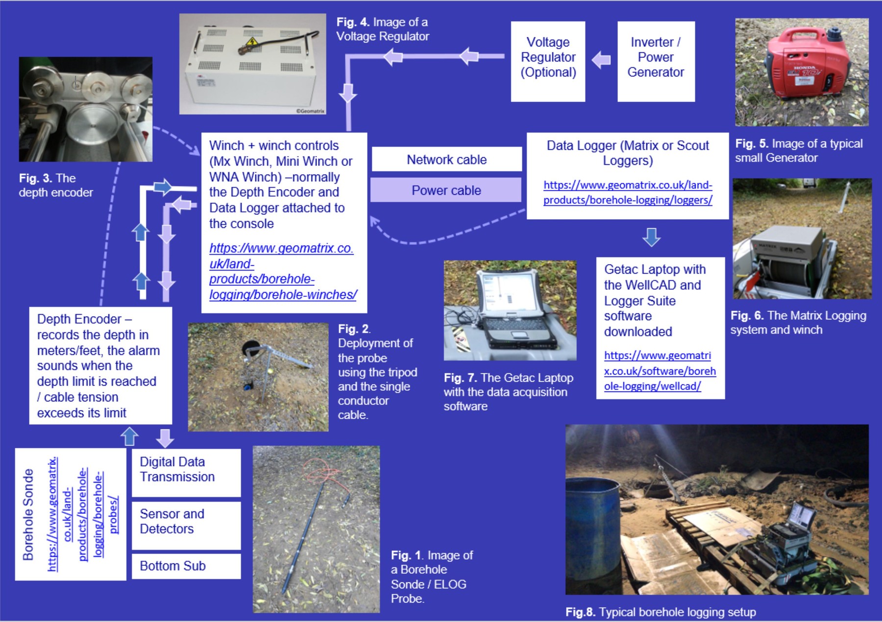
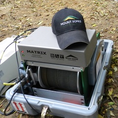
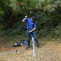
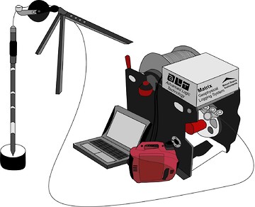
To operate the borehole sondes, proper assembly of the equipment (as shown in Figs 1 and 2) is essential. It is crucial that the operator is fully trained before collecting any data. Once assembled, data acquisition can begin using a portable logger, such as the Scout or Matrix logger, which connects to a Getac laptop running Logger Suite and WellCAD software.
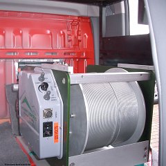
The logger is linked to the winch and borehole sonde via a network cable and a single-core conductor cable, which includes a depth encoder. Additionally, a cable-to-cable stainless steel head is located at the top of the probe as part of the setup.
Powering and Controlling the Equipment
All equipment must be powered via an inverter and can be controlled through a voltage regulator.
Components of the Borehole Sonde
Each borehole sonde is equipped with the source, detectors, power supply, and electronics necessary for transmitting and receiving electronic signals in a 360° radius around the probe axis. These components are designed for complete isolation and robust signal transmission, built to endure high-pressure and high-temperature conditions.