Electrical Resistivity

Electrical Resistivity - Background
The electrical resistivity imaging technique is a powerful tool for differentiating subsurface materials based on their varying ability to conduct or resist electrical current. This makes it invaluable for diverse applications, including landfill investigations, hydrogeological mapping, geological characterization, geotechnical surveys, and downhole logging. The process begins with the injection of a direct current (I) into the ground using current electrodes. As this current propagates through the subsurface, its flow is influenced by the electrical properties of the encountered materials. The resulting distribution of electrical potential is then measured at the surface via potential electrodes.
Resistance is calculated using Ohm’s Law:
“The current that flows in a conductive mass is directly related to the voltage passing through it.”
Ohm’s Law: V = I / R (i.e., Resistance = Voltage / Current)
In other words, the resistance across a cross-sectional area is inversely proportional to its length, measured in Ohm-meters (Ω·m). To obtain true resistivity (as opposed to a singular reading), the apparent resistivity must be calculated using the formula:
Apparent Resistivity (ρₐ) = πaR
This is defined as the resistance calculated at a distance from a point electrode in a uniform half-space of homogeneous ground. Conversely, conductivity, the reciprocal of resistivity (1/ρ), can also be measured in siemens (S/m).
Most metals and metallic sulfides found near the surface, especially in brownfield sites, conduct electricity through the flow of electrons. However, rock-forming minerals tend to be poor conductors, exhibiting high resistance (see Table 1).
These resistance values are determined using Archie’s Law:
“The calculated resistivity within a porous rock containing water-filled pore space and differing matrix grains is equal to the pore fluid resistivity divided by the fractional porosity.”
In cases of ionically pure flow, conduction occurs only through the pore water in the subsurface, as the matrix grains of the lithological formation do not conduct electricity. The resistivity can therefore be measured by the porosity and the pore water fluids present in the material.
Generally, areas with greater resistivity values exceeding 2000 Ohms indicate non-porous igneous or metamorphic rocks, which have subangular, intergranular grains with high cementation. In contrast, sedimentary rocks exhibit lower resistivity values (e.g., around 1000 Ω·m) due to higher porosity. On the other hand, clay-rich soils result in low resistivity readings because of the relationship between clay particles, porosity, quartz (SiO₂) content, and the complex interaction of matrix suction and fluid pressure. Specifically, the greater the porosity and fluid content, the lower the resistivity.
The resistivity value will be greatly influenced by the clay structure. For example, clays with a laminar structure generally do not retain fluid as well as structural or dispersed clays, which tend to have higher water content. London clay, a dispersive clay, has greater expansive qualities and demonstrates this phenomenon. It is important to map expansive clay areas near infrastructure, as these zones swell in the winter and spring (due to heavy rainfall) and shrink in the arid summer months. This shrink-swell relationship is a key factor in causing infrastructural damage and subsidence, especially near older constructions. Therefore, preliminary resistivity surveys are critical in identifying these vulnerable zones.
Areas with low resistivity typically contain pore-water-filled pockets and are often saturated. In environments such as tidal estuaries or areas where saline intrusion is a concern (e.g., coastal aquifers), resistivity can be used to map salinity, as saltwater significantly lowers resistivity. The examination and calculation of pore water resistivity can be done using Archie’s Law.
Archie’s Law for resistivity is given by: P = a(ϱ)⁻ᵐ S⁻ⁿ Pw
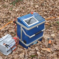
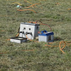
To conduct an Electrical Resistivity Imaging (ERI) or Electrical Resistivity Tomography (ERT) survey, electrodes must be placed at measured intervals across a straight line over the area of investigation. The interval spacing (a) will determine both the resolution and the depth of prospection. Resistivity measurements are taken every set of four electrodes and then re-surveyed at increasing depths—2x the interval spacing (a), 3x a, 4x a, and so on (see Fig. 1).
However, the specific configuration of your survey will depend on the resistivity method used. For example, conducting a Dipole-Dipole array, Wenner array, or Schlumberger array (as outlined in Table 2) will each provide different insights based on the layout and spacing of electrodes.
When conducting an Electrical Resistivity Imaging (ERI) or Electrical Resistivity Tomographic (ERT) survey, the resistivities across a uniform area can be measured as a 2D Pseudo-section. Alternatively, a series of 2D Pseudo-sections can be collected across a gridded (x, y) area to obtain 3D data.
To ensure good ground coupling, electrodes must be pushed into relatively moist ground. In more arid environments where gravel deposits dominate the near surface, a copper sulfate solution can be applied to saturate the ground, ensuring good contact resistance. As an alternative, each electrode should be hammered into the ground to a depth of 50 mm to achieve a reliable connection.